

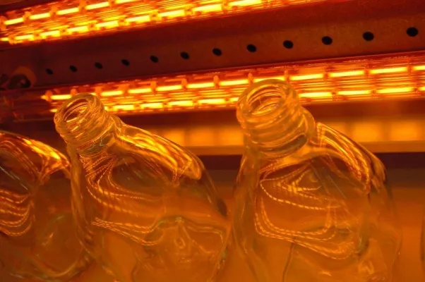
On the glass line, heat is a tool, not a line item. If the furnace climbs too slow, tempering cycles slip and bending repeatability goes sideways. If the thermal field drifts, you start seeing optical distortion, coating defects, and lamination voids that don’t show up until final inspection—when it’s too late. Real energy savings in glass processing start with heating that’s repeatable, quick to respond, and steady under load, without wasting kW. What actually matters under the hood We build heating for glass plants around predictable heat transfer. Medium-wave infrared and NIR elements put energy straight into the glass surface, which cuts soak time and trims convection losses. Quartz and carbon-fiber emitters keep zone control tight, so the thermal profile stays flat and the glass heats evenly—exactly what you need to avoid thermal stress fractures during tempering and bending. Specs are chosen for the floor, not the brochure: 240–480 V compatibility, compact form factors for retrofits, and mounting that drops into existing ovens and laminating presses. Output stability comes down to consistent emissivity and controlled tolerance over long runs, not marketing language. Why this plays in tempering, bending, and lamination In tempering, a faster ramp shortens the cycle while you keep quench consistency steady, so output stays high without pushing the furnace beyond its comfort zone. In lamination, stable zone temperatures knock out edge voids and cut rework, which keeps yield where it should be. In insulating glass sealing, uniform heat across the spacer means you stop fighting uneven adhesive cure—structural integrity improves because the bond cures evenly. The payoff is fewer rejects, less scrap, and a measurable drop in kWh, often 15–25% compared with older heating layouts, because the energy goes into the glass, not into heating air and fixtures. Here are the practical details you’ll run into This heating works with most oven and press designs, but it needs a control strategy that matches. Existing PID and thermocouple interfaces have to line up with the emitter response curve. When you retrofit, plan for the change in thermal mass: new emitters shift heat distribution, so retune zones and confirm temperature uniformity with a calibrated scan. The operating windows are solid, but ambient airflow and line speed changes can move the needle. Lock down the baseline, then set the setpoints that give you repeatable glass quality, every shift.